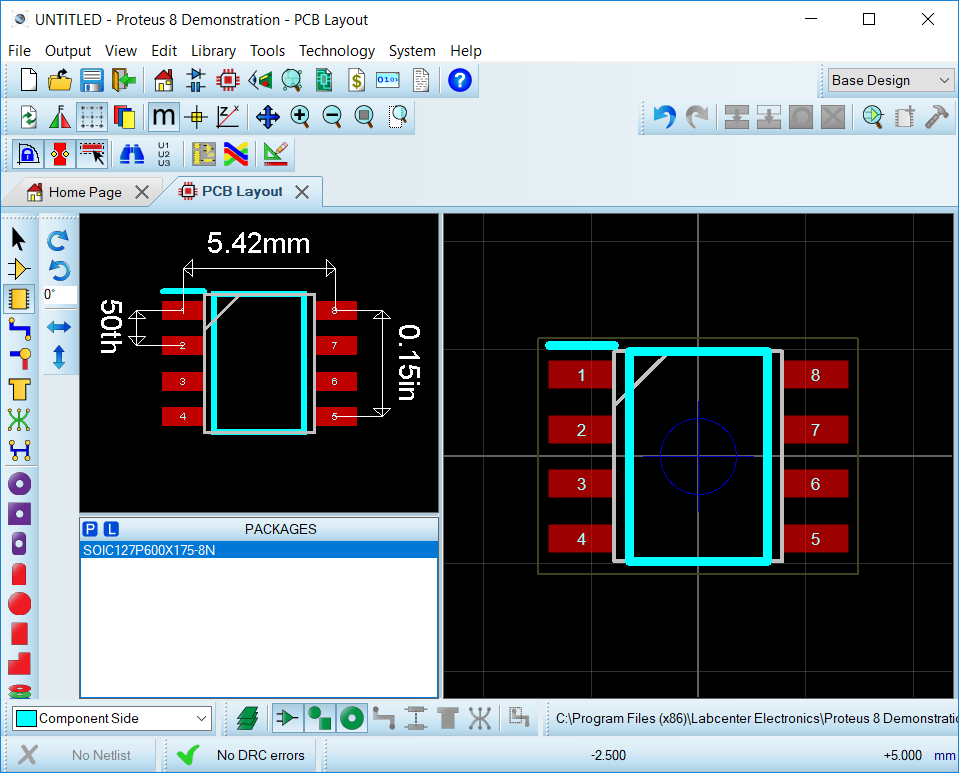


Sometimes you may have different package but you are selecting another component you need to select appropriate PCB as described here for potentiometer(variable resistor) there are many kinds of potentiometer available in market so you need to first check what is available for your then you can select appropriate design, I have mentioned here some of the potentiometers.įor this tutorial I designed a Variable Power Supply for electrolytic capacitors just tzpe cap-elec.Double click the required component and it would appear in your devices and search for other components and place them all in your devices section, some of the components might not have the PCB previews but we can add the PCB layout of them(mentioned later). Here you can check the selected options and click Finish.Ī black colored window would appear that is PCB layout tab, you can switch the tab to schematic captureĬlick on P button it stands for place, a new window would appear, In this window you can search for the components by typing exact names like 1n4007(diode) or simply type diode but if you want to make PCB you have to check that your selected component has a PCB design which is shown in PCB preview. Normally we select No firmware Project, but if we require to work with microcontrollers like 8051, Arduino we select Creat Firmware Project, and select the options accordingly, if anybody wants to know about that just write down a comment, I would guide for that.

Proteus 8 pcb layout software#
If you do not want PCB design just click Next otherwise Mark on create a schematic from the selected template, now you can select Generic single layer or any other layer of your requirement and then click Next, by selecting single layer if you do auto-routing then the software will do only single layer routing(bottom) if you select default and then upon selecting auto-routing the software would double layer(top & bottom layer routing). Now you need to Mark Create a schematic from the selected template then you can either select Default or you can select any templates size normally we select landscape A4, by selecting the Landscape A4 you will have a schematic window as shown in the picture 4

There you can change the Name and Path of the project after setting click N ext A new window called New Project Wizard appears When you launch Prteus click on New Project or press CTRL+N.


 0 kommentar(er)
